What Is an Industrial Panel PC? Components, Types and Applications
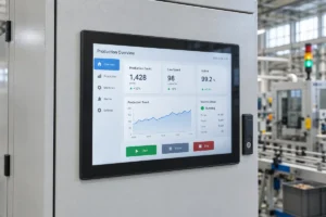
An industrial panel PC is a computer with a built-in display, usually a touchscreen, designed for …
Eagle Touch Engineering Team
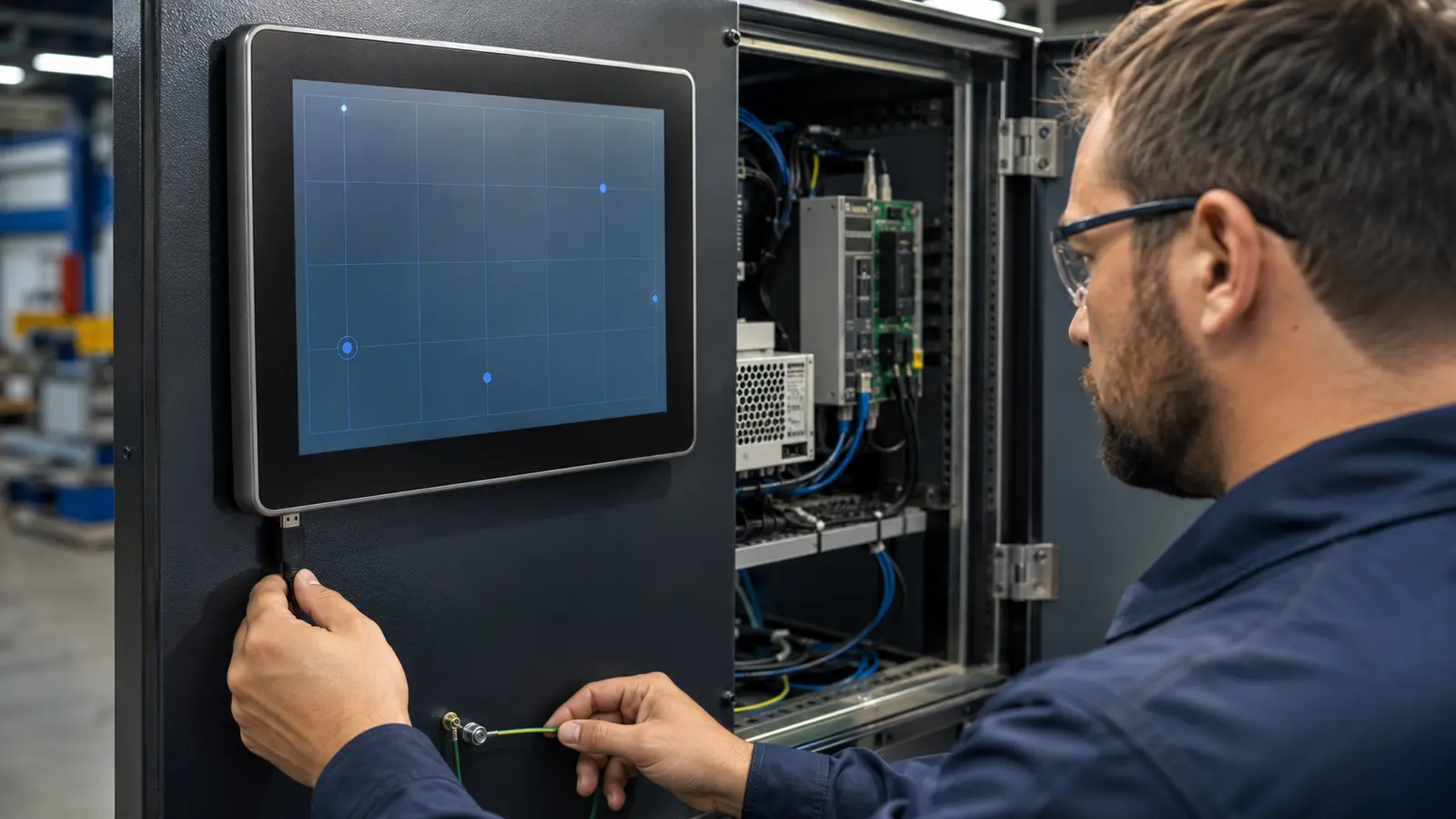
A capacitive touchscreen can pass inspection on the workbench and still fail after it is installed in a machine.
That does not automatically mean the touch panel is defective. Installation changes the electrical and mechanical conditions around it. The final equipment may use a different power source, grounding path or cable route. A gasket or front frame may put pressure on the glass. Water may remain on the surface. An additional protective lens may reduce the touch signal if the sensor and controller were not selected and tuned for the complete stack-up.
The first question should therefore be:
What changed before the problem appeared?
If the touchscreen stopped working after a change in the enclosure, power supply, cable, display electronics, operating system, cover glass or working environment, start there. Replacing the touch panel before isolating the cause often produces the same failure again.
| Symptom | Most Likely Cause Area | First Check |
|---|---|---|
| No touch anywhere | Connection, controller, power or host system | Confirm that the operating system detects the touch controller |
| Ghost touch | EMI, grounding, power noise, water or excessive sensitivity | Test outside the enclosure with a stable power supply |
| Touch point is offset | Mapping, orientation, scaling or firmware | Confirm display resolution, rotation and touch mapping |
| Touch works only sometimes | Cable, USB stability, power cycle, temperature or electrical noise | Record exactly when the failure appears and what restores operation |
| Fixed dead zone | Sensor electrode, FPC, controller channel or local pressure | Run a full-screen line or grid test outside the enclosure |
| Touch activates too easily | Sensitivity, water, metal proximity or controller tuning | Retest with a dry surface and the final glass stack-up |
| Poor glove response | Glass thickness, glove type, sensor design or firmware | Test the actual glove on the complete assembly |
| Unstable touch when wet | Water rejection, grounding, surface condition or bezel drainage | Compare dry, droplets and water-film conditions separately |
| Works before assembly but fails afterward | Mechanical or electrical integration | Remove the unit from the enclosure and repeat the same test |
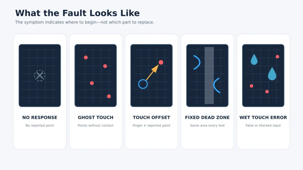
The table identifies where to begin. It does not prove which component is defective. A reliable diagnosis changes one condition at a time and checks whether the failure follows the touchscreen or remains with the machine.
The LCD image is normal, but the system receives no touch input.
Display and touch normally use separate signal paths. HDMI, DisplayPort, VGA, DVI or LVDS may produce a correct image while the USB, I²C, RS232 or controller connection for touch is missing or unstable.
Common causes
First isolation test
Check whether the operating system can see the touch controller. If it cannot, test with a known-good cable and USB port before removing the touchscreen. If touch returns after reconnecting USB or restarting the host, investigate controller detection, power management and startup timing.
For a detailed touch-signal checklist, see Industrial Touch Screen Not Responding.
Ghost touch means the controller reports touch points when nobody is touching the screen. In an industrial HMI, EV charger, kiosk or access terminal, this is more serious than a missed touch because it can trigger an unintended command.
Common causes
EMI and ESD should not be treated as the same event. EMI is usually continuous or appears when nearby equipment operates. ESD is a short discharge that may reset the controller, cause a temporary failure or, in a severe case, damage a component.
First isolation test
Test the touchscreen or complete touch monitor outside the enclosure with a stable independent power supply. During component-level development, compare touch performance with the display and backlight circuits active and inactive where the design allows it. In the complete machine, switch motors, inverters, charging modules and other major loads on and off one at a time. If false points appear only under a particular condition, the evidence points toward power noise, grounding, shielding, cable routing or system integration rather than a random sensor defect.
See Touch Screen Interference: How to Check EMI, Grounding and Power Noise for a deeper interference test.
Touch offset means the reported position does not match the finger. Jumping coordinates move unpredictably while the finger remains in one place.
Common causes
Modern USB PCAP systems operating as standard HID devices often do not need routine calibration. If the offset appeared after changing resolution, rotation, motherboard or operating system, check mapping first. Repeated calibration can hide the symptom without correcting the installation or configuration error.
First isolation test
Draw continuous lines across a full-screen test grid. A consistent offset across the entire screen usually suggests mapping or alignment. Random movement suggests electrical noise. A fixed local distortion is more likely to involve pressure, sensor damage or a local electrode problem.
Related guide: Industrial Touch Screen Accuracy Loss.
An intermittent fault works normally under some conditions and fails under others. The timing is more useful than the symptom alone.
Record whether the failure appears:
First isolation test
Do not change several components at once. Reproduce the failure, change one condition and repeat. If reconnecting the same cable restores operation, inspect the connector, strain relief, USB detection and controller power. If temperature or machine load changes the result, log those conditions instead of classifying the unit as “randomly defective.”
A dead zone is an area that repeatedly fails to detect touch while the rest of the screen works. It may appear as an unresponsive edge, corner, strip or isolated region.
Possible causes
First isolation test
Use a full-screen line or grid test. Remove the touchscreen from the enclosure and repeat the test with a known-good host, cable and power source.
If the same area remains dead in every test condition, a sensor, FPC or controller-channel defect becomes more likely. If the area recovers after loosening the frame or removing the unit, review the enclosure clearance, gasket compression, tape position and screw load.
A projected-capacitive controller can sometimes detect a finger very close to the glass. A small amount of proximity response is not necessarily a fault. It becomes a problem when the screen triggers unintended commands or becomes unstable near the bezel.
Common causes
First isolation test
Clean and dry the surface, then test with the final cover glass, bonding method and enclosure. Do not reduce sensitivity until water, grounding, metal distance and EMI have been checked. Lowering sensitivity may remove false input but create a new glove or edge-response problem.
“Supports glove touch” is not a complete specification.
Touch performance depends on:
A touchscreen that works with a thin nitrile glove may not work with a thick insulated work glove. A solution tuned for dry gloves may behave differently when water is present.
First isolation test
Test the actual glove on the complete production-intent assembly. Include the final glass, bonding, bezel, power supply and operating environment. If the product must support both wet operation and gloves, validate that combination separately.
Sensitivity tuning also has a trade-off: increasing gain can improve glove response but reduce noise margin. Hardware, firmware and the mechanical stack must be considered together.
Waterproofing and wet-touch performance solve different problems.
A front panel can meet an IP protection requirement and still produce false touches when wet.
Possible symptoms
First isolation test
Test dry glass, isolated droplets and a water film as separate conditions. Also check whether the bezel traps water at the edge. Controller tuning cannot fully compensate for a structure that allows conductive liquid to remain over the active surface indefinitely.
For outdoor equipment, drainage, sealing, grounding, controller tuning and real-machine water testing should be reviewed together.
This is one of the most useful diagnostic clues in an OEM project.
If the same touchscreen works outside the machine, installation has introduced a new condition. Typical causes include:
A bench test proves that the component works under bench conditions. It does not validate the complete machine.
This pattern is common in EV chargers, kiosks and industrial control cabinets: the touch assembly operates normally with a laboratory power supply, but false or missed inputs appear after the high-power electronics and metal enclosure are added. The correct response is to isolate the added conditions in sequence—not to keep replacing the same panel.
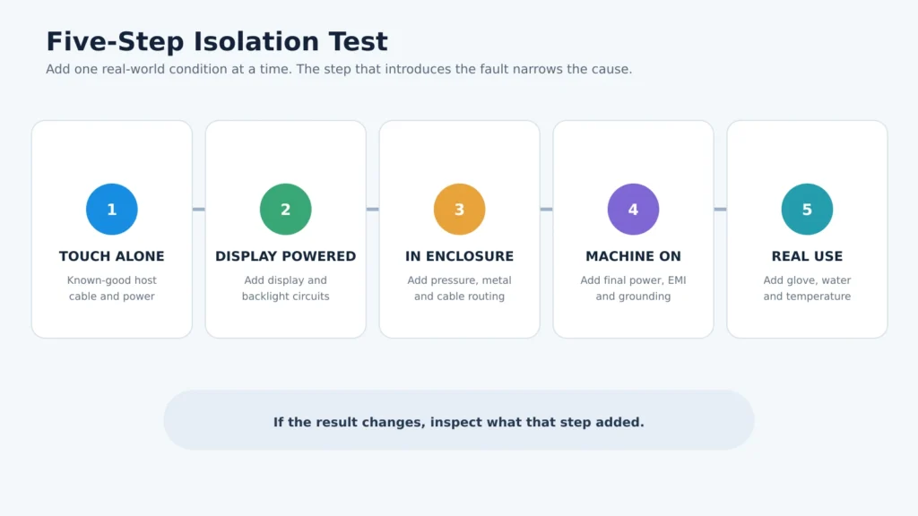
Use a known-good host, touch cable and stable power source. Complete a full-screen grid test.
For touch-panel or display-module development, compare the result before and after the LCD and backlight circuits are active. If the problem appears only with the display system powered, inspect display/backlight drive noise, power integrity, grounding and signal-cable separation. When testing a complete touch monitor, this integration has already been completed by the monitor supplier; begin by confirming that the monitor operates normally outside the customer’s final equipment.
If the result changes, check frame pressure, gasket compression, screw load, FPC routing, metal clearance and enclosure grounding.
Operate motors, relays, inverters, chargers and switching power modules. Compare a stable independent supply with the production power source.
Use the actual glove, water condition, cleaning liquid, temperature range, cable length and user interface.
The step that makes the fault appear usually identifies the part of the system that needs further investigation.
System integration causes many touch problems, but the panel itself can fail. A touchscreen-side defect becomes more likely when:
These observations are stronger evidence than a single test inside one machine. Cross-testing should be documented before deciding whether to replace the touch panel, controller, cable or host-side hardware.
For a custom industrial capacitive touchscreen or industrial touch monitor project, confirm the following before approving mass production:
Do not approve the touchscreen only because it works on a desk. Approve it after it works in the equipment it was selected for.
When asking a supplier to investigate, send evidence that allows the fault to be reproduced:
“Touch not working” is not enough information. A short video and a controlled cross-test often save more time than replacing parts at random.
Eagle Touch supports industrial PCAP touchscreens, open-frame monitors and panel PCs for OEM equipment. If your touchscreen works during sample testing but fails after assembly, send us the failure video, installation photos, interface, operating system, glass stack-up, power information and affected quantity.
We can help review whether the evidence points toward the sensor, controller, firmware, cable, grounding, power, display-circuit interference, enclosure pressure or working environment before recommending replacement or redesign.
If you are planning a new project, also include the target size, annual quantity, mounting drawing, glove or wet-touch requirement and operating environment. These details allow the touch solution to be evaluated before sampling rather than after field installation.
Yes. A capacitive touch controller needs a stable electrical reference. If the controller, LCD frame, host and metal enclosure do not have a consistent grounding design, electrical noise can appear as false, missed or unstable touch input.
Many USB HID PCAP systems do not need routine calibration. An offset may instead come from display rotation, resolution, scaling, multi-monitor mapping, active-area alignment or firmware. Calibration should only be used when the system and controller require it.
Not always. Reliable operation through thick glass depends on sensor design, controller capability, glass thickness, air gaps, bonding, noise level and firmware. Increasing gain alone may improve response but also increase false touches.
The operating load may introduce EMI, ground-potential changes or power-supply noise. Test with an independent supply, separate touch cables from power wiring and compare the grounding condition before replacing the panel.
No. Front IP65 addresses water and dust ingress under defined test conditions. Stable operation with water on the glass depends on wet-touch tuning, surface condition, drainage, grounding and the complete front structure.
An industrial panel PC is a computer with a built-in display, usually a touchscreen, designed for …
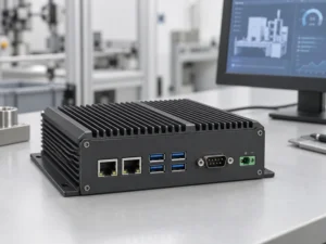
An embedded PC is a computer configured to work as part of a machine or larger …
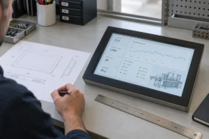
Start with the software the panel PC must run and the conditions it must fit. Then …
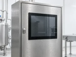
Choosing an industrial panel PC IP rating starts with two questions: what dust and water exposure …
Share your application, requirements, or current challenge. Our team will review the details and recommend a practical way forward.