Custom PCAP and Resistive Touch Screens for Industrial Equipment
We manufacture custom PCAP and resistive touch screens for industrial displays, control panels, kiosks, EV chargers, and embedded equipment. Size, cover glass, FPC, controller, interface, and bonding method can be adjusted around your LCD and device structure.
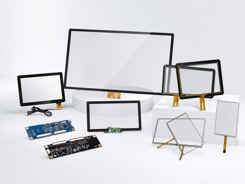
PCAP and Resistive Touch Screens We Supply
We design, manufacture, and supply PCAP touch screens and resistive touch screens for industrial displays, control panels, kiosks, EV chargers, and embedded equipment.
Standard touch screens can be used as a starting point. For custom projects, the size, cover glass, FPC, sensor structure, surface treatment, and LCD bonding can be adjusted according to the application.
- PCAP touch screens
- 4-wire resistive touch screens
- 5-wire resistive touch screens
- Custom touch panels
- Custom cover glass
- AG / AR / AF surface treatment
- Custom FPC and sensor structure
- Touch screen bonded with LCD
Custom Options for Your Touch Screen Design
Touch screen customization is usually decided by the glass, sensor, FPC, interface, controller, and final use environment.
- Cover glass size and shape
- Cover glass thickness
- Black border and logo printing
- Transparent window design
- AG / AR / AF surface treatment
- PCAP or resistive sensor
- FPC direction and length
- Connector position
- USB / I²C / RS-232 interface
- Controller board selection
- Glove or wet touch support
- Thick cover glass
- Air bonding or optical bonding
- Waterproof front structure
- Outdoor or high-brightness display use
Choose PCAP or Resistive Touch for Your Application
Touch technology is selected based on screen size, operation method, controller solution, interface, front structure, and working environment.
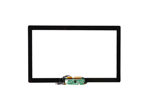
Projected Capacitive (PCAP)
For glass-front HMI, multi-touch control, sealed panels, kiosks, EV chargers, and outdoor equipment.
- Typical size range: 7" to 55"
- Controller solutions: EETI, ILITEK, Goodix
- Interface: USB, I²C, RS-232
- Touch functions: multi-touch, glove touch, water-drop tuning
- Customization: size, shape, logo, cover glass thickness, FPC design
- Applications: commercial, industrial, kiosk, EV charger, outdoor equipment
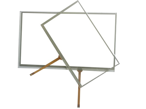
Resistive (4-Wire / 5-Wire)
For stylus operation, heavy gloves, single-touch control, indoor industrial panels, and legacy systems.
- Typical size range: 4.3" to 24"
- Type: 4-wire and 5-wire resistive touch
- Controller solution: EETI
- Touch function: single-touch industrial control
- Operation: stylus, heavy glove, oil, or water touch
- Applications: industrial control panels, indoor equipment, legacy systems
Both PCAP and resistive touch screens can be supplied as separate touch panels or integrated touch assemblies, depending on the project. You can also check our reference touch screen sizes as a starting point.
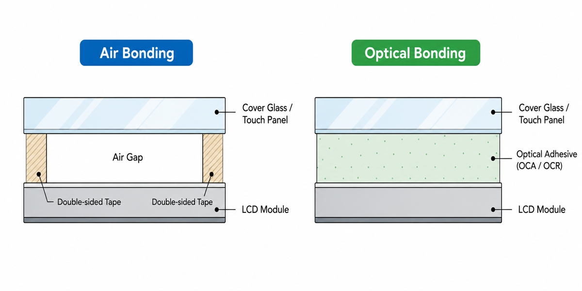
Bonding Method Options
We provide air bonding and OCA / OCR optical bonding for touch screen assemblies used with LCD modules.
Choose by Application, Cost, and Readability
The bonding method is mainly selected by application environment, readability requirement, repair strategy, and project budget.
- Indoor and easy repair: air bonding is often enough
- Outdoor and high brightness: optical bonding should be reviewed
- Sealed or humid environments: fogging risk should be considered
Air Bonding
A practical option for indoor applications, cost-sensitive projects, and products where easier repair or replacement is important.
OCA / OCR Optical Bonding
Recommended for outdoor, high-brightness, sealed, or thick-glass applications where lower reflection, better readability, and reduced fogging risk are required.
Optical bonding is not required for every touch screen project. For a deeper comparison, read optical bonding vs air bonding or our guide to outdoor display optical bonding.
What to Send for a Touch Screen Quote
A drawing is the fastest way to quote a custom touch screen. If the drawing is not ready, we can start with the LCD model, target size, photos, and application details.
- LCD model or LCD drawing
- Touch screen size
- Active area and view area
- Cover glass outline drawing
- Cover glass thickness
- FPC direction and length
- Connector position
- Interface: USB, I²C, or RS-232
- Indoor or outdoor use
- Glove, wet, or stylus operation
- Bonding requirement if needed
- Quantity and project stage
For replacement projects, photos of the current touch screen, LCD label, FPC, connector, and front structure are usually enough for an initial direction.
Built for Industry, Infrastructure & Public Systems
From factory equipment and EV chargers to kiosks and transportation systems, our touch, display, and computing solutions are developed around how each application works in the field.

Energy & Infrastructure
Touch and display systems for EV chargers, energy terminals, outdoor cabinets, and other public infrastructure.

Industrial Automation
Touch monitors and panel PCs for machine controls, operator stations, production equipment, and industrial cabinets.

Self-Service & Kiosks
Touch screens, monitors, and panel PCs for kiosks, payment terminals, smart lockers, and automated service equipment.

Transportation Systems
Displays and panel PCs for ticketing, check-in, passenger information, and transportation control terminals.
Common Questions About Custom Touch Screens
Answers to common questions about PCAP touch screens, resistive touch screens, cover glass customization, LCD matching, bonding options, and quotation details.
Do you supply both PCAP and resistive touch screens?
Yes. We supply PCAP touch screens, 4-wire resistive touch screens, and 5-wire resistive touch screens for industrial displays, control panels, kiosks, EV chargers, and embedded equipment.
Can you customize the touch screen size and match our LCD?
Yes. The outline size, view area, active area, cover glass size, and FPC direction can be customized based on your LCD drawing, housing limitation, or target size.
Can you customize cover glass and printing?
Yes. Cover glass thickness, shape, black border, logo, icons, transparent window, and AG / AR / AF surface treatment can be reviewed according to the application.
Can PCAP touch screens support gloves or water?
Yes, but glove and wet touch performance depends on the cover glass, bonding method, controller tuning, grounding, and final enclosure structure.
Can you make thick cover glass touch screens?
Yes. Thick cover glass can be reviewed for industrial, outdoor, or impact-resistant applications. The sensor structure, controller, bonding method, and mechanical design need to match the final glass thickness.
Do we need optical bonding?
Not always. Air bonding may be enough for many indoor projects. Optical bonding is usually reviewed for outdoor, high-brightness, sealed, thick-glass, or long-lifecycle display applications.
What information is needed for a quotation?
Please share the LCD model or drawing, touch screen size, cover glass drawing if available, interface requirement, FPC direction, operating environment, and estimated quantity. For replacement projects, photos of the current touch screen, LCD label, FPC, connector, and front structure are also helpful.
A Manufacturing Partner You Can Rely On
We combine established manufacturing experience, disciplined quality management, and dependable support to give OEM customers confidence throughout every project.
Years of industrial manufacturing experience provide the practical foundation to support demanding OEM projects.
Defined procedures, consistent inspection, and documented controls help maintain quality throughout manufacturing.
Our experience includes projects involving listed companies and Fortune 500 organizations, where consistency, confidentiality, and dependable support are essential.
Reference Touch Screen Sizes
Standard PCAP and resistive touch screen models can be used as a starting point for size selection. Final dimensions, cover glass, FPC, interface, controller, and bonding method can be adjusted based on your drawing or application.
PCAP Touch Screens — Standard Models
| P/N | Size | Thickness | Window VA (mm) | Sensor Outline (mm) | Cover Lens (mm) |
|---|---|---|---|---|---|
| ET097F8614 | 9.7" | 3.9mm | 196.75 × 148.3 | 199.75 × 151.3 | 253.77 × 188.77 |
| ETCG101A83-2.0 | 10.1" | 2.0mm | 217.96 × 136.6 | 228 × 149 | 229.60 × 151.00 |
| ET101F8058 | 10.1" | 2.9mm | 217.96 × 136.6 | 229.96 × 151.5 | 254.96 × 172.6 |
| ET101F8059 | 10.1" | 2.9mm | 222.5 × 125 | 234.5 × 140 | 247 × 150 |
| ETCCG104A03-1.0 | 10.4" | 2.5mm | 213.6 × 161.00 | 237.98 × 187.17 | 255.20 × 202.50 |
| ET104F8060 | 10.4" | 2.9mm | 211 × 158.4 | 235.2 × 175.4 | 245.1 × 192.5 |
| ETCG104A06-1.0 | 10.4" | 2.85mm | 212.20 × 159.40 | 239 × 179.4 | 242.00 × 183.00 |
| ET116F8023 | 11.6" | 2.9mm | 257 × 146 | 270 × 159 | 287 × 176 |
| ETCG121A19-1.0 | 12.1" | 1.9mm | 247 × 186.6 | 257.75 × 201.95 | 259.75 × 203.95 |
| ET121F8062 | 12.1" | 2.0mm | 246.76 × 185.32 | 260 × 200.1 | 274.16 × 220.9 |
| ET133F8063 | 13.3" | 2.0mm | 295 × 166.6 | 307.88 × 181.12 | 335 × 197 |
| ET140F8064 | 14" | 2.0mm | 311 × 176 | 322 × 190 | 335 × 200 |
| ETCG150A30-3.0 | 15" | 2.45mm | 304.10 × 228.10 | 304.10 × 228.10 | 327.50 × 255.00 |
| ET150F8066 | 15" | 2.0mm | 304 × 228.01 | 323 × 243.5 | 364 × 288 |
| ETCG156A08-2.0 | 15.6" | 2.4mm | 343.54 × 192.83 | 367.30 × 216.20 | 380.5 × 234.58 |
| ET156F8069 | 15.6" | 3.9mm | 344 × 194 | 358 × 210 | 383.91 × 233 |
| ETCG170A11-2.0 | 17" | 2.45mm | 338.92 × 271.34 | 338.92 × 271.34 | 364.42 × 299.33 |
| ET170F8068 | 17" | 2.9mm | 338.92 × 271.34 | 356.92 × 290.84 | 377 × 309 |
| ETCG185A13-1.0 | 18.5" | 3.4mm | 410.80 × 231.40 | 433.80 × 283.00 | 460 × 283.00 |
| ET185F8071 | 18.5" | 3.9mm | 410.8 × 231.40 | 428 × 249.9 | 448.8 × 269.4 |
| ETCG190A13-1.0 | 19" | 3.4mm | 377.32 × 302.06 | 403.32 × 331.06 | 403.32 × 331.06 |
| ET190F8072 | 19" | 2.9mm | 377.32 × 302.06 | 395 × 320.26 | 421 × 346 |
| ET195F8074 | 19.5" | 2.7mm | 433 × 240.36 | 447.4 × 257.8 | 472.5 × 280.9 |
| ETCG215A56-1.0 | 21.5" | 3.4mm | 478.00 × 269.80 | 478.00 × 269.80 | 508 × 303.80 |
| ETCG215A72-2.0 | 21.5" | 2.45mm | 476 × 267.50 | 492 × 288.61 | 494 × 290.61 |
| ETCG236A04-1.0 | 23.6" | 4.4mm | 522.65 × 295.20 | 549.20 × 326.05 | 587.00 × 356.00 |
| ET236F8078 | — | 2.7mm | 522.28 × 294.22 | 542.16 × 318.44 | 555.5 × 343 |
| ET236F8079 | — | 2.7mm | 522.26 × 294.22 | 542.16 × 318.44 | 555.5 × 343 |
| ET238F8080 | 23.8" | 2.7mm | 527.04 × 296.46 | 544 × 316.5 | 570 × 342 |
| ET270F8082 | 27" | 3.3mm | 598 × 336 | 618.2 × 360.45 | 658 × 416 |
| ETCG320A02-1.0 | 32" | 3.35mm | 698.95 × 393.42 | 721.50 × 416.65 | 757.12 × 450.60 |
| ETCG430A02-1.0 | 43" | 4.4mm | 943.20 × 535.50 | 973.00 × 561.50 | 994.20 × 587.30 |
| ETCG550A01-1.0 | 55" | 4.3mm | 1210.8 × 680 | 1251.6 × 716.42 | 1299 × 770 |
4-Wire Resistive Touch Screens — 10.1" to 24"
| P/N | Size | Thickness | Outside Dimension | View Area | Active Area |
|---|---|---|---|---|---|
| ET-4101A0 | 10.1" | 1.4mm | 224 × 168.5 | 207 × 156.5 | 203 × 152.5 |
| ET-4101A1 | 10.1" | 1.1mm | 233 × 143.8 | 223.4 × 132.2 | 221.4 × 130.2 |
| ET-4101A7 | 10.1" | 1.4mm | 235 × 145.8 | 223.42 × 133.65 | 221.42 × 131.65 |
| ET-4104A0 | 10.4" | 1.4mm | 225.55 × 172.95 | 215 × 162.2 | 211.2 × 158.8 |
| ET-4106A0 | 10.6" | 1.4mm | 227 × 175 | 215 × 165 | 215 × 165 |
| ET-4121AO | 12.1" | 2.0mm | 260.6 × 198.5 | 250.5 × 188.9 | 243.76 × 182.32 |
| ET-4121A1 | 12.1" | 2.0mm | 271 × 206 | 254 × 192 | 248 × 186 |
| ET-4121A2 | 12.1" | 2.0mm | 275.8 × 178 | 264.1 × 166.2 | 261.1 × 163.2 |
| ET-4141A0 | 14.1" | 2.0mm | 319 × 204 | 306 × 192 | 302 × 188 |
| ET-4150A0 | 15" | 2.0mm | 322 × 247 | 310.5 × 236 | 304 × 228 |
| ET-4150A2 | 15" | 2.0mm | 321 × 247 | 310.5 × 236 | 304 × 228 |
| ET-4151A0 | 15.1" | 2.0mm | 346.2 × 217 | 331.2 × 207 | 327.2 × 203 |
| ET-4156A0 | 15.6" | 2.0mm | 358 × 208.5 | 348 × 196 | 346 × 194 |
| ET-4170A0 | 17" | 2.0mm | 355 × 288 | 341.5 × 275 | 337 × 269 |
| ET-4170A1 | 17" | 2.0mm | 362 × 278 | 331 × 250 | 320 × 240 |
| ET-4171A0 | 17.1" | 2.0mm | 382.2 × 239.5 | 367.2 × 229.5 | 363.2 × 225.5 |
| ET-4185A0 | 18.5" | 2.0mm | 429.37 × 253.6 | 413.39 × 234 | 409.79 × 230.4 |
| ET-4190A0 | 19" | 2.0mm | 392 × 318 | 376 × 303 | 367 × 293 |
| ET-4190A1 | 19" | 2.0mm | 396 × 323 | 377 × 304 | 375 × 300 |
| ET-4190A2 | 19" | 2.0mm | 441.8 × 273 | 418.6 × 253.6 | 415 × 250 |
| ET-4191A0 | 19.1" | 2.0mm | 426.8 × 275 | 412 × 259 | 406 × 253 |
| ET-4192A0 | 19.2" | 2.0mm | 500 × 109.2 | 481.1 × 92 | 478.08 × 89.64 |
| ET-4200A0 | 20" | 2.0mm | 462.8 × 272 | 446.8 × 253.2 | 442.8 × 249.08 |
| ET-4216A0 | 21.6" | 2.0mm | 500 × 292.6 | 481.5 × 272.6 | 477.5 × 268.6 |
| ET-4220A0 | 22" | 2.0mm | 488 × 310 | 473.5 × 295 | 471 × 293.8 |
| ET-4220A1 | 22" | 2.0mm | 491 × 318 | 477 × 300 | 475.6 × 297.6 |
| ET-4230A0 | 23" | 2.0mm | 534 × 313 | 514 × 291 | 510 × 287 |
4-Wire Resistive Touch Screens — Small Sizes
| P/N | Size | Thickness | Outside Dimension | View Area | Active Area |
|---|---|---|---|---|---|
| ET-4043A0 | 4.3" | 1.0mm | 105.5 × 67.2 | 99 × 57.6 | 96.4 × 55 |
| ET-4047A0 | 4.7" | 1.0mm | 113.7 × 69.3 | 106.88 × 61.15 | 105.28 × 60.15 |
| ET-4050A3 | 5" | 1.1mm | 120.2 × 73.5 | 116.2 × 67.5 | 111.2 × 63.7 |
| ET-4057A0 | 5.7" | 1.4mm | 132.5 × 104.7 | 123 × 94.7 | 116 × 87.7 |
| ET-4060A0 | 6" | 1.4mm | 143.5 × 88 | 135.08 × 77.67 | 132.48 × 75.07 |
| ET-4061A0 | 6.1" | 1.4mm | 148 × 82 | 138.2 × 74 | 136.2 × 72 |
| ET-4062A0 | 6.2" | 1.4mm | 155.2 × 89 | 140.7 × 80.4 | 137.52 × 77.22 |
| ET-4065A0 | 6.5" | 1.4mm | 155 × 89.3 | 142.8 × 80 | 142.8 × 80 |
| ET-4069A0 | 6.9" | 1.4mm | 167 × 93 | 159.3 × 84.4 | 157.3 × 82.4 |
| ET-4070A0 | 7" | 1.4mm | 164.8 × 103.8 | 155.3 × 94.3 | 152.4 × 91.44 |
| ET-4070A1 | 7" | 1.4mm | 163.5 × 102.5 | 154.4 × 93.44 | 151.4 × 90.44 |
| ET-4070A2 | 7" | 1.4mm | 168 × 94 | 159.3 × 86 | 157 × 83.8 |
| ET-4070A3 | 7" | 1.4mm | 164.9 × 100 | 157 × 90 | 155 × 88 |
| ET-4070A4 | 7" | 1.4mm | 165 × 106 | 155 × 93.5 | 152 × 91 |
| ET-4071A0 | 7.1" | 1.4mm | 164.2 × 103.2 | 155 × 94 | 153.4 × 92.44 |
| ET-4078A0 | 7.8" | 1.4mm | 185.7 × 118.4 | 172.6 × 10³ | 169 × 99 |
| ET-4078A2 | 7.8" | 2.3mm | 174 × 132.2 | 163.5 × 123.9 | 158 × 118.7 |
| ET-4080A0 | 8" | 1.4mm | 183 × 141 | 164.8 × 124.8 | 161.8 × 121.8 |
| ET-4081A0 | 8.1" | 1.4mm | 192.8 × 115.9 | 182.1 × 105.4 | 178.64 × 101.36 |
| ET-4084A0 | 8.4" | 1.4mm | 184.8 × 149 | 172.8 × 130.5 | 168.8 × 126.5 |
| ET-4084A2 | 8.4" | 1.4mm | 199 × 118.5 | 189.9 × 108.6 | 185.76 × 104.6 |
| ET-4084A3 | 8.4" | 1.4mm | 187 × 141 | 173.5 × 131 | 170.5 × 128 |
| ET-4089A0 | 8.9" | 1.4mm | 213.36 × 129.55 | 198.16 × 116.55 | 196.07 × 114.4 |
| ET-4089A1 | 8.9" | 1.1mm | 205 × 125 | 200 × 118.2 | 198.4 × 117 |
| ET-4090A0 | 9.0" | 1.4mm | 210.7 × 112.08 | 201.1 × 115.15 | 198 × 112.08 |
| ET-4100A0 | 10" | 1.4mm | 255.2 × 61.4 | 249.79 × 54.2 | 70.09 × 53 |
5-Wire Resistive Touch Screens — Standard Models
| P/N | Size | Thickness | Outside Dimension | View Area | Active Area |
|---|---|---|---|---|---|
| ET-5102A0 | 10.2" | 2.0mm | 145.9 × 235 | 136.11 × 224.9 | 133.2 × 222 |
| ET-5104A0 | 10.4" | 2.0mm | 174 × 229 | 162.2 × 215 | 158.8 × 211.2 |
| ET-5121A0 | 12.1" | 2.0mm | 200 × 265 | 188.9 × 250.5 | 182.32 × 243.76 |
| ET-5121A2 | 12.1" | 2.0mm | 178 × 275.8 | 166.2 × 264.1 | 163.2 × 261.1 |
| ET-5141A0 | 14.1" | 2.0mm | 204 × 319 | 192 × 306 | 188 × 302 |
| ET-5150A0 | 15" | 2.0mm | 247 × 322 | 236 × 310.5 | 228 × 304 |
| ET-5156A0 | 15.6" | 2.0mm | 215 × 362.8 | 196.8 × 374.54 | 192.8 × 343.54 |
| ET-5170A0 | 17" | 2.0mm | 288 × 355 | 275 × 341.5 | 269 × 337 |
| ET-5185A0 | 18.5" | 2.0mm | 429.37 × 253.6 | 412.97 × 234 | 409.37 × 230.4 |
| ET-5190A0 | 19" | 2.0mm | 318 × 392 | 303 × 376 | 293 × 367 |
| ET-5190A1 | 19" | 2.0mm | 323 × 396 | 304 × 377 | 300 × 375 |
| ET-5191A0 | 19.1" | 2.0mm | 276 × 426 | 260 × 414 | 256 × 410 |
| ET-5200A0 | 20" | 2.0mm | 329 × 432 | 308 × 410 | 303 × 405 |
| ET-5216A0 | 21.6" | 2.0mm | 292.6 × 500 | 275 × 483.5 | 270 × 478.5 |
| ET-5220A0 | 22" | 2.0mm | 310 × 488 | 295 × 473.5 | 293.8 × 471 |
Let’s Discuss Your Requirements
Share your application, requirements, or current challenge. Our team will review the details and recommend a practical way forward.