An industrial touch screen is not selected by size and touch technology alone. It must work with the operator, cover glass, controller, host system, enclosure and electrical environment as one system.
For an OEM project, the first question is not simply “PCAP or resistive?” It is: what level of product does the equipment need, how will it be operated, and what must the final assembly withstand?
This guide explains the decisions that matter before a drawing is released or a sample is approved.
Touch Screen, Touch Display, Monitor or Panel PC?
These terms are often used interchangeably, but they describe different product levels.
Product level
What it includes
Typical use
Touch panel / touch screen
Touch sensor, FPC and controller solution; PCAP versions may include custom cover glass
Added to an existing LCD or embedded display design
Touch display module
Touch panel combined with an LCD by air bonding or optical bonding
Connected to an embedded mainboard through LCD and touch interfaces
Touch monitor
LCD, touch, display controller, video inputs, power circuitry and mounting structure
Connected to an industrial PC or other external host
Panel PC
Touch display, computer, memory, storage, I/O and enclosure
Complete HMI or data terminal
Defining this level at the beginning prevents a common quotation problem: one side is discussing a touch panel while the other expects a complete monitor.
The operator touches the surface with a finger, glove or stylus.
The sensor detects a change in capacitance or physical pressure.
The touch controller filters the signal and calculates the coordinates.
The host receives the coordinates through USB, I²C or another supported interface.
The sensor is only one part of this chain. A suitable panel can still perform poorly if the controller, grounding, cable routing, enclosure or firmware is not matched to the finished equipment.
PCAP vs Resistive Touch Screen
Projected capacitive and resistive touch are the two practical choices for most industrial OEM projects. Infrared and SAW systems remain useful in some large-format or specialized applications, but they are not normally the first choice for a compact, flat and sealed equipment interface.
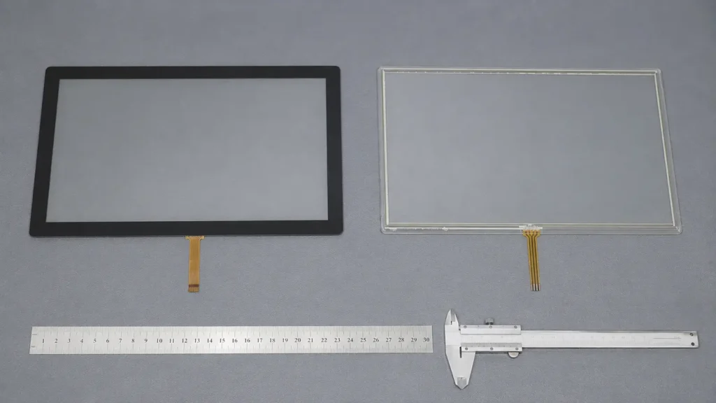
Left: projected capacitive touch panel with custom cover glass. Right: conventional resistive touch panel with a flexible top layer.
Projected Capacitive Touch
A PCAP sensor uses a conductive electrode pattern to detect changes in an electric field. It normally sits behind a glass surface.
PCAP is a strong choice when the product requires:
a flat glass front
multi-touch or gesture control
good optical clarity
frequent operation without wear to an exposed flexible film
custom cover glass, printing or surface treatment
Industrial PCAP is not automatically reliable in every enclosure. Thick cover glass, non-conductive gloves, water, switching power supplies, long cables and nearby metal can reduce the available signal margin. The sensor, controller and firmware must be tested in the final assembly.
A conventional resistive touch screen uses a flexible PET top layer and a rigid glass substrate separated by spacer dots. Pressure brings the conductive layers into contact and produces the touch coordinates.
Resistive touch is often the more predictable choice when the equipment requires:
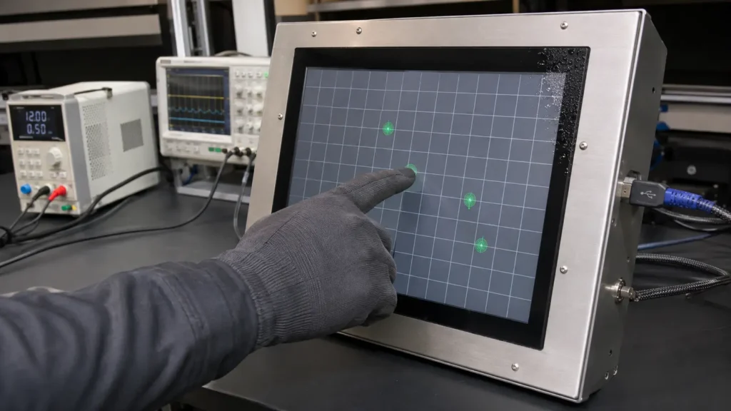
operation with thick or non-conductive gloves
input with a plastic stylus or other non-conductive object
simple single-point control
compatibility with a legacy system
lower sensitivity to electrical noise
Its trade-offs are the flexible top surface, lower optical transmission than PCAP and mechanical wear over time. Four-wire and five-wire designs also have different durability and calibration characteristics. These are covered in the industrial resistive touchscreen guide.
Quick Comparison
Requirement
PCAP
Resistive
Finger input
Excellent
Good
Multi-touch
Normally supported
Normally not supported on conventional 4- or 5-wire designs
Thick, non-conductive glove
Must be evaluated and tuned
Normally suitable
Plastic stylus or tool
Not normally detected
Suitable
Front surface
Rigid cover glass
Flexible PET film
Water on the surface
Behaviour must be defined and tuned
Droplets normally do not create pressure input, but sealing is still required
Electrical noise
Depends strongly on grounding, shielding and controller margin
Generally less sensitive
Typical application
Modern HMI, kiosk, EV charger, glass-front equipment
Industrial control, test equipment, legacy replacement
The choice is not about which technology is newer. It is about which one gives adequate operating margin in the intended application. See the detailed PCAP vs resistive comparison when both options remain possible.
Select the Technology from the Real Input Method
“Glove operation” is not a complete requirement. Nitrile, leather, cotton, cut-resistant and insulated gloves behave differently. Thickness alone does not describe their electrical properties.
The same applies to water. A project may require one of three different behaviours:
ignore isolated droplets
accept a wet finger
suspend touch during heavy water exposure
These behaviours are not interchangeable. They should be defined before controller tuning and tested with the actual glove, liquid and cover-glass stack. The glove-compatible touch screen guide explains the main variables in more detail.
Application condition
Practical starting point
What must be verified
Modern graphical HMI
PCAP
UI targets, multi-touch, grounding and EMC behaviour
Heavy glove or universal stylus input
Resistive, or tuned PCAP if a glass front is essential
Actual glove and input tool
Outdoor kiosk or EV charger
PCAP with a sealed glass front
Wet behaviour, sunlight readability, temperature and enclosure design
Frequent cleaning
Glass-front PCAP is often easier to clean
Cleaning liquid, water rejection and edge sealing
Legacy panel replacement
Match the original technology first
Outline, active area, FPC, pinout, controller and calibration
Electrically noisy machinery
Resistive for simple input, or PCAP with controlled grounding and shielding
Complete powered system under worst-case operating conditions
Touch Controller and Interface Selection
The touch interface is separate from the LCD video interface. HDMI, DisplayPort, LVDS and eDP carry the image; USB, I²C or a serial interface normally carries the touch coordinates.
USB
USB HID is usually the simplest choice for a touch monitor or PC-based system. It is easy to test independently and is supported by many Windows, Linux and Android platforms. Host compatibility should still be checked, particularly for older operating systems, locked-down terminals and custom Android builds.
I²C
I²C is common in embedded equipment where the touch controller connects directly to the mainboard. It can reduce external cabling, but it requires the correct voltage, pin definition, driver and firmware integration. It should not be treated as a plug-and-play substitute for USB.
Serial Interface
RS-232 remains useful in some legacy industrial systems and replacement projects. Confirm the protocol, connector, baud rate, power arrangement and operating-system support before assuming compatibility.
Cover Glass, Impact and Front Sealing
For a PCAP design, the cover glass defines much of the product’s appearance and front-surface durability. A drawing should specify:
outside dimensions and viewing area
thickness and glass material
chemical strengthening or thermal tempering where applicable
edge finish, holes and cut-outs
black border, logo and transparent windows
AG, AR or AF surface treatment where required
Thicker glass does not automatically mean a higher IK rating. Impact performance also depends on glass material, strengthening process, edge condition, support width, adhesive, enclosure structure and the completed test assembly. The touch screen cover glass design guide covers these factors separately.
The same distinction applies to IP ratings. IEC 60529 classifies the ingress protection of an enclosure. A touch panel can support a sealed front design, but it does not make the finished equipment IP65 by itself. Gasket compression, bonding, openings and the customer’s cabinet all affect the result.
Air Bonding or Optical Bonding?
Air bonding fixes the touch panel around the LCD perimeter and leaves an air gap. It is suitable for many indoor applications and is normally easier to repair.
Optical bonding fills the gap between the touch panel and LCD with transparent adhesive. It reduces internal reflection and can improve apparent contrast in strong ambient light. It also removes the internal air gap where condensation could otherwise form.
Optical bonding is not necessary for every industrial display, and it does not replace correct brightness, thermal or enclosure design. Use the optical bonding guide to decide whether the optical benefit justifies the added process and rework requirements.
Information Required Before Quotation
A drawing is the best starting point. When no drawing is available, the LCD model and clear photographs can support an initial review.
Item
Information to provide
Product level
Touch panel, touch display module, monitor or panel PC
Display reference
LCD model, LCD drawing, resolution and orientation
Mechanics
Outside size, active area, viewing area, thickness and FPC direction
Input
Finger, glove, stylus, wet finger or water rejection
Touch technology
PCAP, 4-wire resistive or 5-wire resistive
Interface
USB, I²C, RS-232 or required controller output
Front design
Cover glass, printing, openings, surface treatment and sealing target
Environment
Indoor/outdoor use, temperature, moisture, contamination, vibration and electrical noise
Integration
Air bonding, optical bonding or touch panel only
Project
Sample quantity, annual demand, required certifications and expected production life
Providing these details early is faster than selecting a standard touch panel by diagonal size and redesigning it after the enclosure is complete.
Validate the Final Assembly, Not Only the Touch Panel
A bench test with an uncovered sensor cannot represent the finished product. Before approval, test the same glass, LCD, controller, cables, power supply, metalwork and software planned for production.
The validation plan should include:
touch accuracy, edge response and multi-touch where required
the actual gloves, stylus and operating gestures
defined wet-touch or water-rejection behaviour
cold start, wake, restart, rotation and operating-system recognition
operation from the intended power supply and cable length
touch stability while motors, chargers, inverters or other noise sources are active
temperature and humidity conditions relevant to the equipment
mechanical fit, glass clearance and gasket compression
ESD and EMC testing required by the finished product’s compliance plan
Repeat the relevant tests after changing the LCD, cover glass, controller, firmware, cable, power supply or enclosure. Controller tuning cannot compensate for every hardware or grounding problem. If unexplained false touches appear, use a structured touch screen interference check rather than increasing sensitivity at random.
Common Specification Mistakes
Selecting by diagonal size only
Two touch panels with the same nominal size can have different outside dimensions, active areas, viewing areas and FPC positions.
Treating glove support as a yes-or-no feature
Glove performance depends on material, thickness, cover glass, sensor design, controller and firmware. Test the actual glove.
Assuming thick glass guarantees IK10
Glass thickness is only one part of the impact-resistant assembly. IK performance must be verified on the defined final structure.
Calling the touch panel waterproof
Sealing and touch behaviour are different. The enclosure prevents ingress; controller firmware manages droplets and wet input.
Tuning before the final hardware is available
PCAP settings approved on an open bench may become unstable after the LCD, metal bezel, power supply and long cable are installed.
Ignoring production changes
A new LCD, controller revision or adhesive stack can change optical or touch performance. OEM programs need component control and revalidation rules, not just a successful first sample.
Frequently Asked Questions
Which touch technology is best for industrial equipment?
PCAP is normally preferred for a sealed glass front, multi-touch and modern graphical interfaces. Resistive touch remains valuable for heavy gloves, universal stylus input, simple single-touch control and many legacy systems.
Can an industrial PCAP touch screen work with gloves?
Yes, if the sensor, cover glass, controller and firmware provide sufficient signal margin. The actual glove must be tested in the completed equipment.
Is an industrial touch screen waterproof?
Not by itself. The touch panel can be designed into a sealed front, but the IP rating applies to the tested enclosure or finished product. Water rejection by the controller is a separate requirement.
Does PCAP require calibration?
PCAP normally does not require routine calibration. Mapping or configuration may still be needed after changes to screen orientation, firmware, host settings or the display layout. Conventional resistive systems may require calibration.
What should be sent for a replacement touch screen?
Send the original touch-panel outline, active area, FPC and connector details if available. Clear photographs of the front, rear, FPC code, LCD label and installed structure are also useful. Matching only the diagonal size is not sufficient.
Final Recommendation
A reliable industrial touch screen is the result of correct technology selection and controlled system integration. Start with the real input method and operating environment, define the product level and interfaces, then validate the complete assembly before production.
For an OEM review, send the LCD model or drawing, required touch method, glass design, interface, operating environment and expected quantity. Eagle Touch can evaluate the touch panel, controller and integration approach before the design is released.