Industrial Display Monitors for OEM Integration
Project-defined monitor assemblies for equipment programs — focused on mechanical fit and interface compatibility.
Industrial Display Monitors for Equipment Integration
We supply industrial display monitor assemblies designed for integration into equipment, terminals, kiosks, and infrastructure platforms.
Available in open-frame, panel-mount, and VESA configurations, monitors are specified based on enclosure fit, interface compatibility, and deployment environment.
Supply is structured for OEM and system integration programs where configuration consistency and long-term availability planning are required.

Typical Configuration Coverage
Common specification ranges for OEM and system integration projects. Final configuration is defined per application.
| Size | 7"–32"+ standard industrial sizes |
|---|---|
| Resolution | Defined by panel selection per size |
| Brightness | Standard to high-brightness options |
| Touch | PCAP or resistive (use-case driven) |
| Signal Interfaces | HDMI / VGA / DVI / LVDS |
| Mounting | Open-frame / Panel-mount / VESA / Custom |
| Operating Temperature | Standard or wide-temperature (project-defined) |
Share your target size, interface, and mounting constraints — we’ll confirm configuration direction and compatibility.
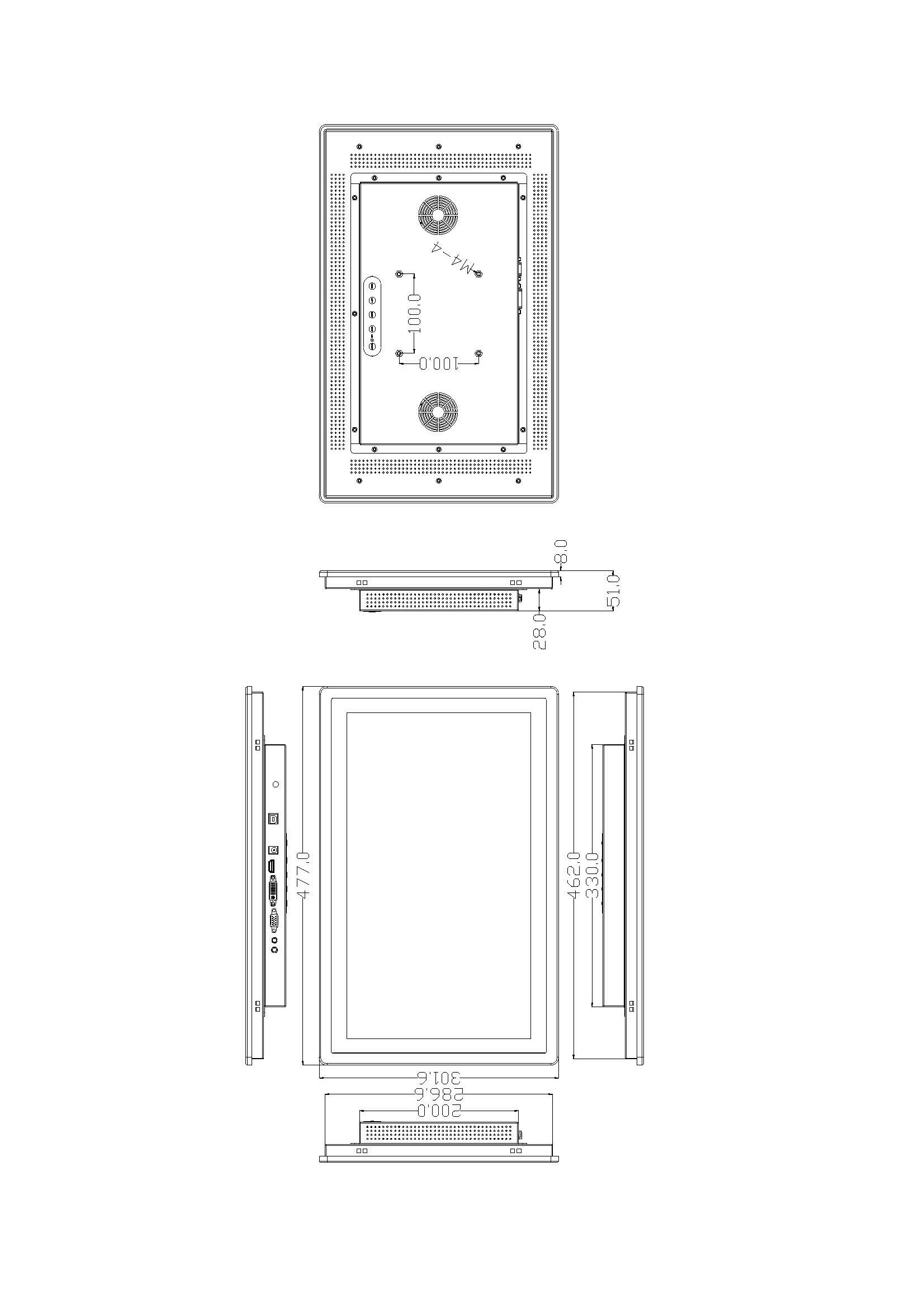
Size Reference for Equipment Integration
Select your target display size to review typical mechanical layouts, interface expectations, and touch configurations used in equipment projects.
Configuration Selection Guide
Evaluate structure direction based on integration method, interface architecture, and deployment conditions.
Display Configuration Types
Common structural configurations used in equipment integration. Each type includes integration notes and project-defined options.

Open Frame
Designed for internal mounting inside custom housings. Bracket method and front sealing are defined by enclosure design.
View Open Frame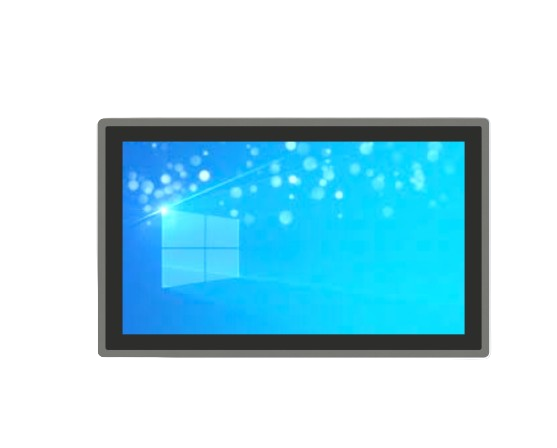
Panel Mount
Installed into a panel cutout with bezel retention. Front-side installation and sealing strategy are project-defined.
View Panel Mount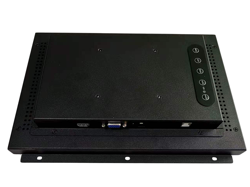
VESA Mount
Configured with VESA mounting patterns for arm, bracket, or wall integration.
View VESA OptionsFor outdoor or harsh deployments, configuration is defined by exposure, temperature range, and enclosure sealing.
View Outdoor ConfigurationsDeployment Constraints That Drive Configuration
In equipment programs, monitor configuration is shaped by duty cycle, enclosure design, service access, and site conditions. These constraints typically define the structure and build approach.
24/7 Duty Cycle
Thermal approach and component choices are set for continuous operation.
Service Access
Mounting and cable routing are aligned to maintenance and replacement needs.
Enclosure Integration
Cutout, bracket method, and front sealing are defined by the cabinet design.
Site Conditions
Temperature, sunlight, dust-water, and handling risk shape the final build.
Configuration Control in OEM Programs
In long-term equipment programs, monitor configuration is managed through defined revision baselines and formal change notification to maintain integration stability across production batches.
- Revision Baseline: the approved configuration becomes a controlled reference build (form-fit-function).
- PCN Discipline: component or design changes follow structured notification with agreed lead time.
- Traceability: revisions, scope of change, and effective dates are documented for program continuity.
Defined Control Points
- BOM Freeze Point: configuration enters revision control after sample approval.
- Change Lead Time: aligned with validation cycle and inventory planning requirements.
- Approved Alternatives: documented where risk mitigation or supply continuity requires it.
Lifecycle Stability for Long-Term Equipment Programs
OEM deployments often span multiple years. Display configuration must remain stable to avoid redesign, revalidation, and field disruption during the program lifecycle.
Panel Lifecycle Awareness
Panel selection considers manufacturer lifecycle status and discontinuation risk.
Batch-to-Batch Consistency
Mechanical fit and optical performance remain aligned across production cycles.
Continuity Planning
Potential supply or component risks are evaluated in the context of program duration.
Program Review Documentation
Documentation is provided under agreed scope and NDA where required.
- Engineering package: outline drawing, cutout reference, mounting notes
- Interface definition: signal mapping, touch USB/HID notes
- BOM revision record: controlled baseline and approved alternatives
- PCN / ECN notices: documented change scope and effective dates
- Production traceability: batch identification (program-defined)
- Compliance documentation: provided when applicable
Review expectations (required documents, PCN lead time, program duration) can be aligned during project discussion.
Structured Workflow
Clear inputs. Defined deliverables. From specification to production.
Confirm constraints and define configuration direction.
- Size / brightness
- Interface list (HDMI / DP / LVDS / eDP)
- Mounting method
- Operating temperature
- Touch requirements (glove / wet if needed)
Engineering sample and validation against operating conditions.
Pilot run, then repeatable production with controlled revisions.
Share what you have — we will respond with configuration direction and next steps.
Industrial Display Monitor FAQ
Key engineering and integration questions.
Engineering Review
Send your application details. We respond with configuration direction and next steps.