Industrial Open Frame Monitor for OEM Equipment Integration
Custom open frame monitor assemblies built to fit your enclosure, controller, and production requirements. For kiosks, machine cabinets, EV charging stations, laboratory devices, industrial terminals, and HMI equipment.
Open Frame Monitors Made to Fit Your OEM Equipment Design
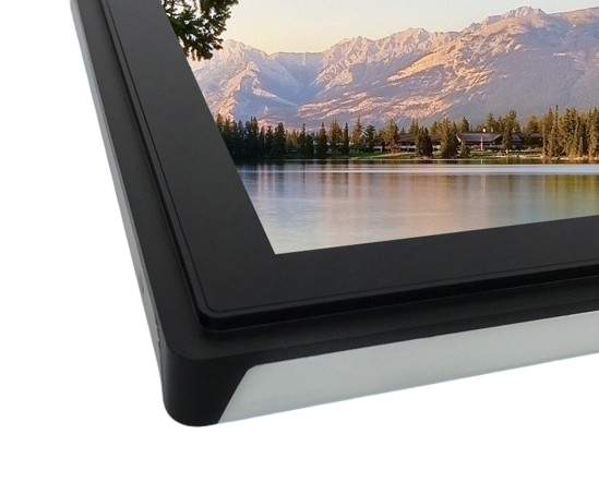
When a standard enclosed monitor cannot fit inside your equipment, an open frame monitor provides a ready-to-integrate display assembly for your own enclosure, control panel, kiosk, EV charging station, or industrial machine.
Each unit can include the LCD panel, controller board, metal mounting frame, cables, touch screen, and front glass. This helps your engineering team avoid sourcing and matching separate display components.
Eagle Touch helps match the open frame monitor to your equipment structure, controller I/O, touch use, front glass, and production plan before sample build.
Samples, pilot runs, and small-batch orders can be supported before mass production to verify mechanical fit, display function, optional touch performance, and assembly process. For other mounting structures, explore our full range of industrial display monitors and touch monitors.
Open Frame Monitor Configuration Options for OEM Projects
Start with your screen size, enclosure structure, interface, touch use, and working environment. Eagle Touch then helps confirm the display configuration that fits your equipment design.
- Target screen size or visible area
- Cut-out drawing or housing photo
- Controller model or preferred video input
- Touch, cover glass, brightness, and environment requirements
| Configuration Item | Typical Options / Confirmation Method |
|---|---|
| Screen size | 7” – 32” |
| Resolution | Selected by screen size, LCD availability, and project requirements |
| Brightness | Standard / high-brightness / sunlight-readable option |
| Touch | PCAP / resistive / no-touch |
| Cover glass | Thickness, AG / AR / AF, printing, edge treatment |
| Bonding | Air bonding / optical bonding |
| Mechanical structure | Front-mount / rear-mount / enclosure-defined frame structure |
| Cable & connector layout | Rear / side cable exit, connector position, cable length by project |
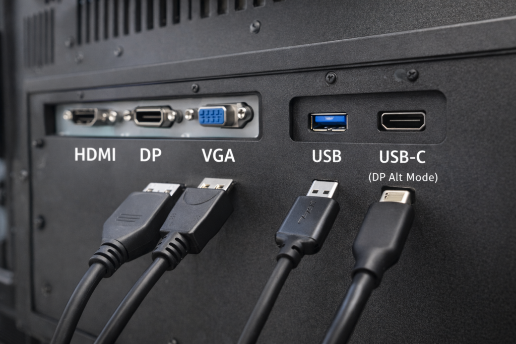
| Video input | HDMI / VGA / DVI / DP (LVDS / eDP by project) |
| Touch interface | USB |
| Power input | Matched to equipment power design |
| Environment | Indoor / semi-outdoor / equipment-defined operating conditions |
| Production control | Approved specification and revision tracking |
Need a size-based starting model? View our open frame touch monitor model list for common 7” to 32” PCAP and resistive touch configurations.
Open Frame Monitor Applications in OEM Equipment
Open frame monitors are used when the display must be built into the equipment structure, enclosure, or control interface instead of working as a separate external monitor.
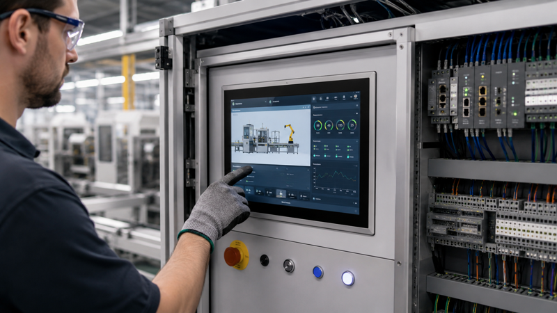
Automation & Control Cabinets
Embedded HMI displays for machine control panels, cabinet doors, and factory operator stations.
Key points: fixed mounting, glove operation, cable routing, EMI conditions, and controller interface.
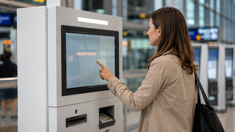
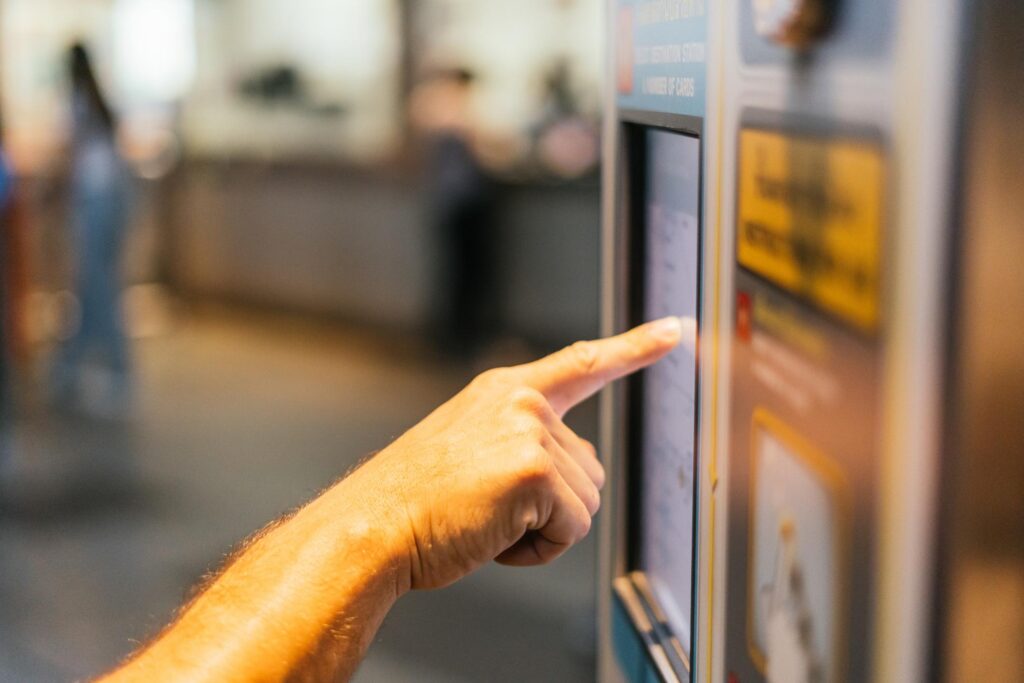
Kiosks & Self-Service Terminals
Open frame touch displays for ticketing, check-in, payment, information, and interactive service terminals.
Key points: public touch use, cover glass, front protection, service access, and long operating hours.
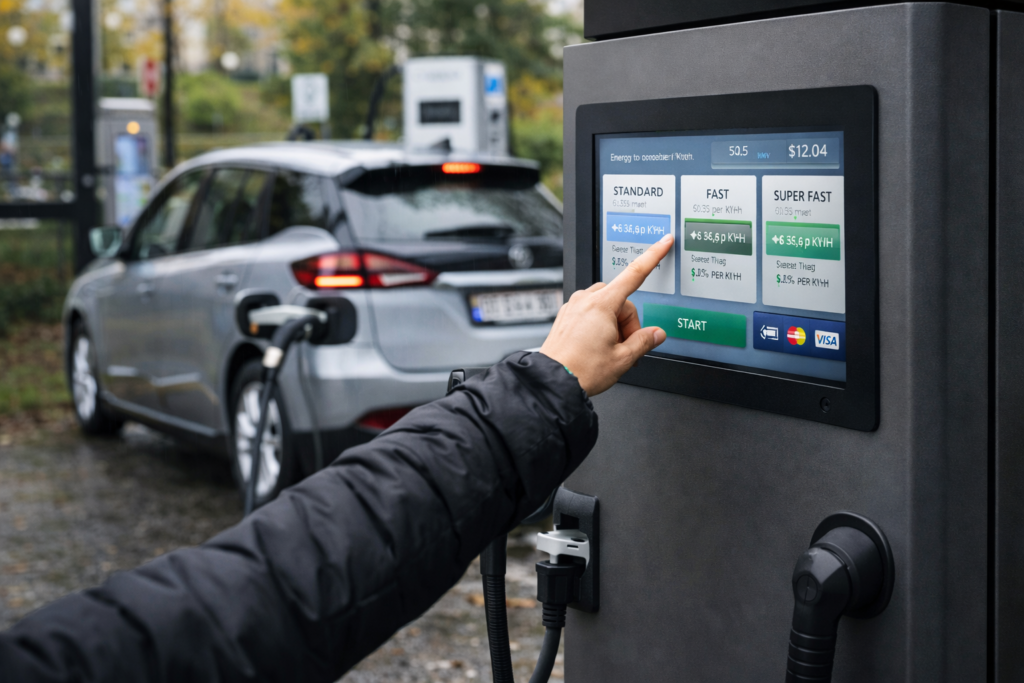
EV Charging & Outdoor Terminals
Displays for EV chargers, outdoor payment terminals, energy equipment, and infrastructure control interfaces.
Key points: brightness, front glass, sealing design, temperature conditions, and stable supply.
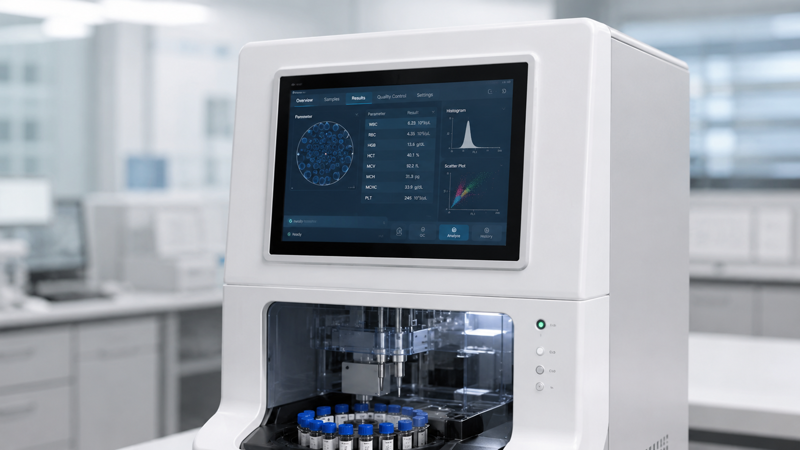
Laboratory & Diagnostic Equipment
Embedded displays for laboratory analyzers, diagnostic instruments, test devices, and healthcare terminals.
Key points: enclosure fit, stable interface, cleaning conditions, optical clarity, and supply continuity.
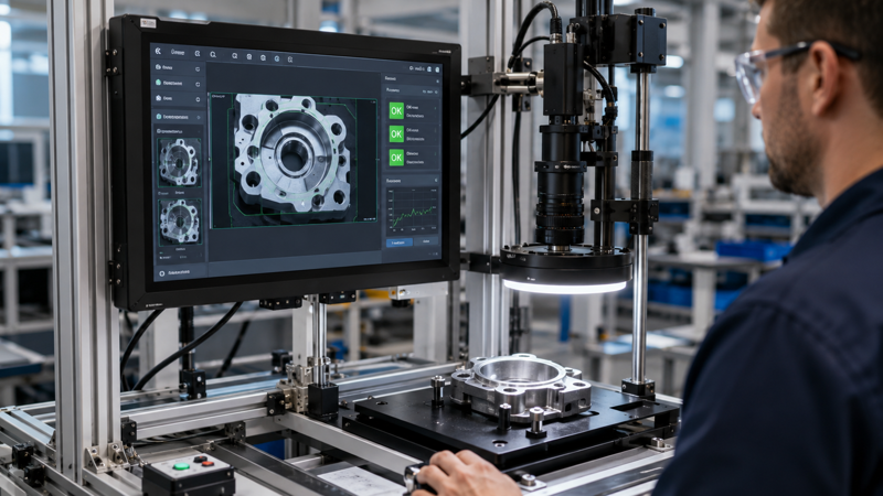
Inspection & Measurement Systems
Display interfaces for machine vision stations, measurement benches, test systems, and inspection equipment.
Key points: image visibility, fixed installation, operator input, interface compatibility, and repeatable assembly.
Retail, POS & Vending Equipment
Open frame displays for POS terminals, vending machines, ordering systems, and embedded retail equipment.
Key points: touch durability, front glass, compact installation, payment interface layout, and maintenance access.
Fit an Open Frame Monitor into Your Equipment Enclosure
For open frame integration, the screen size is only the starting point. The opening, depth, mounting points, connectors, and cable direction all need to match the final equipment design.
Example reference for cut-out, mounting, depth, and cable direction.
A photo with marked dimensions is often enough to find early fit risks.
NDA can be arranged before sharing detailed enclosure drawings.
What Should Be Checked Before Sample Build?
These details help avoid enclosure rework, cable interference, and assembly problems after the monitor sample is built.
Opening and Visible Area
Check opening size, bezel overlap, tolerance, active area, and visible area before fixing the enclosure design.
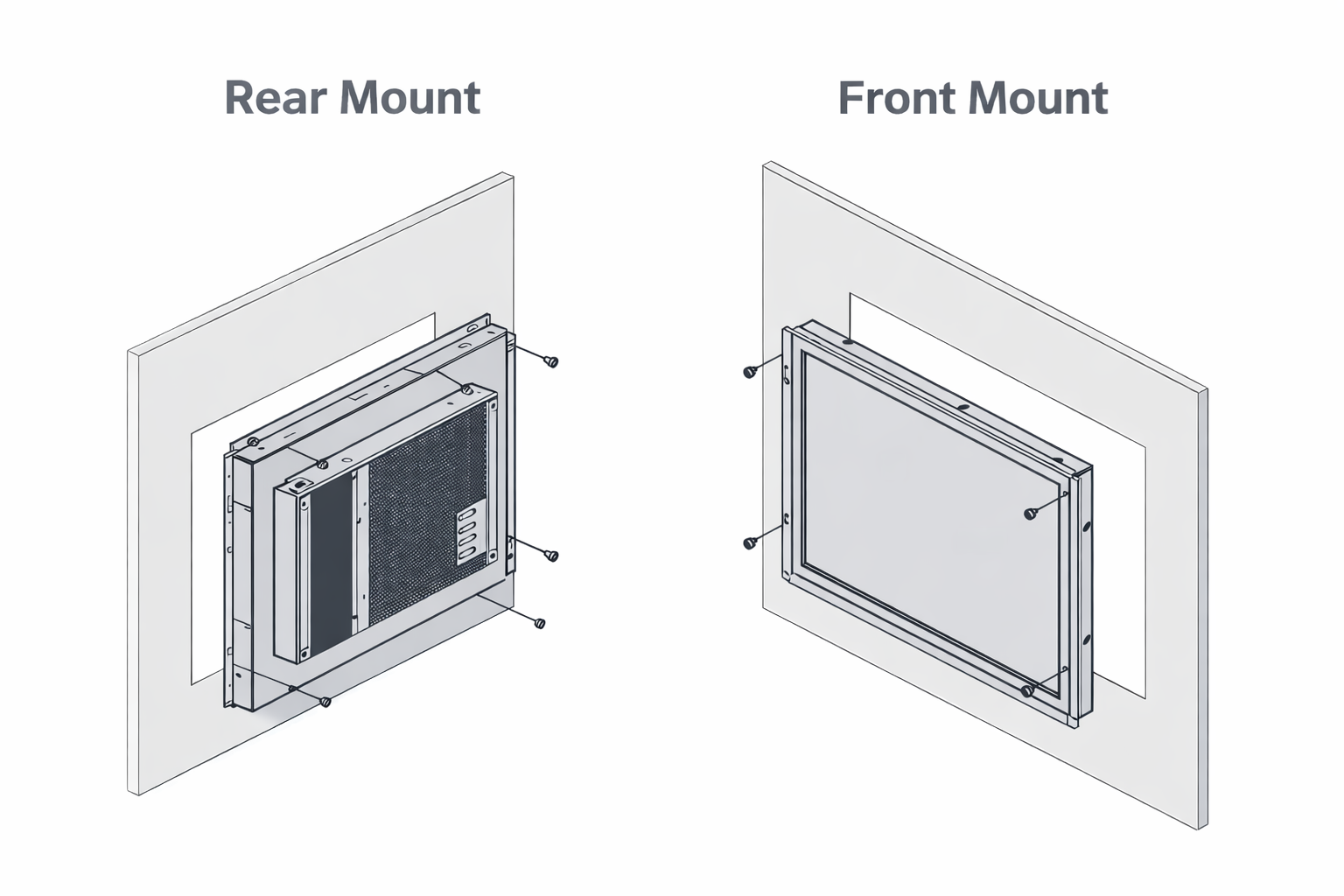
Front or Rear Installation
Confirm front-mount, rear-mount, bracket position, mounting holes, and service access based on your housing.
Back Clearance
Leave space for the LCD module, controller board, connector height, cable bend, and final assembly.
Connector and Cable Direction
Check connector location, cable exit direction, routing space, and strain relief before sample build.
Cut-out drawing or housing photo with marked dimensions
Mounting concept, if already decided
Depth limit, connector clearance, or cable routing restriction
Match the Open Frame Monitor to Your Controller I/O
After the monitor fits the enclosure, the next risk is signal, touch, and power compatibility. Eagle Touch helps confirm the controller board, video input, touch communication, and power connection before sample build.
- Video signal: HDMI / VGA / DVI / DP (LVDS / eDP by project)
- Touch communication: USB touch controller for PCAP or resistive touch configuration
- Power connection: matched to the available system power and equipment layout
- Controller board: selected according to LCD panel, input signal, touch use, and installation space
Controller I/O, touch signal, power rail, and connector access should be confirmed before the sample is built.
Touch, glass, surface treatment, and bonding should be selected according to the final operating environment.
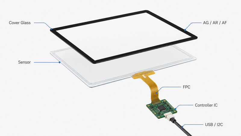
Front Structure Options for Touch and Glass
Select the touch type, cover glass, surface treatment, and bonding method based on how the equipment will be used, cleaned, viewed, and protected.
Need only a touch panel or cover glass? View our industrial touch screen solutions.
- PCAP touch: multi-touch, glove use, custom cover glass
- Resistive touch: pressure input or legacy control
- No-touch: display-only equipment with external controls
- Cover glass: thickness, printing, AG / AR / AF, edge processing
- Bonding: air or optical bonding for readability and protection
Open Frame, Panel Mount or VESA Mount?
Choose the monitor structure by installation method, enclosure design, and service access—not only by screen size.
Open Frame Monitor
Best for kiosk housings, machine enclosures, and OEM equipment where the display becomes part of the customer’s mechanical design.
Choose this when the monitor must be built into your own enclosure without a full standalone housing.
Panel Mount Monitor
Best for control cabinets, operator panels, industrial consoles, and equipment front panels.
Choose this when the monitor needs a front bezel or panel-mounted structure for front-side installation.
VESA Mount Monitor
Best for machine-side displays, wall mounts, arms, brackets, and workstation installations.
Choose this when the monitor can be mounted externally instead of embedded into the enclosure or front panel.
For front-panel installation, review our panel mount monitor solutions. For bracket, arm, or wall installation, review our VESA mount monitor options.
Check Each Build Before Shipment
For OEM open frame monitor projects, quality control should cover display function, touch response, signal input, power connection, mechanical assembly, appearance, and packing before shipment.
- Display, touch, signal, and power function check
- Mechanical assembly, cable routing, and appearance inspection
- Packing, labeling, and documentation reviewed by project scope
What We Check Before Shipment
Inspection items can be confirmed according to the project configuration, application environment, and target market requirements.
LCD and Image Check
Check display function, brightness direction, image output, and visible defects according to the approved configuration.
Touch and Communication Test
Verify PCAP or resistive touch response, USB communication, touch orientation, and basic operation before shipment.
Signal and Power Check
Confirm video input, controller board, power connection, cable access, and basic system compatibility.
Mechanical and Appearance Check
Check frame assembly, cover glass, cable routing, connector position, labels, packing, and visible appearance.
Project compliance requirements such as CE, FCC, RoHS, REACH, packaging, labeling, or documentation can be reviewed according to the target market and order scope.
From Sample Build to Controlled Repeat Production
For OEM open frame monitor projects, the process should move from requirement review to sample validation, specification approval, and controlled repeat orders.
- Requirements are reviewed before sample build
- Samples are checked against the agreed configuration
- Repeat orders follow the approved project specification
Review Requirements
Check screen size, enclosure drawing, cut-out, mounting method, interface, touch use, brightness, operating environment, and order plan.
Confirm Configuration
Confirm the LCD, frame structure, controller board, touch type, cover glass, bonding method, power input, and drawing reference.
Build and Validate Sample
Sample units are built to verify mechanical fit, display function, touch performance, interface compatibility, and assembly process.
Approve and Repeat
After the sample and specification are approved, repeat orders can follow the agreed configuration. If key items change, the revision is reviewed before future production.
Open Frame Monitor Selection & Procurement FAQ
Common questions before selecting, sampling, or integrating an open frame monitor into OEM equipment.
Need an Industrial Display, Touch Screen, or Panel PC?
Send your size, brightness, touch type, interface, mounting method, environment, and target quantity — early-stage projects are welcome.